In this post I’ll share the details of the design of my custom H4 Quadcopter Frame. It’s a very sturdy yet light aluminum frame designed to use 10″ propellers and 700Kv to 1000Kv motors. I fly 10x4.5 propellers with 800Kv motors on 2.65A 4S LiPo batteries with excellent results. This is perhaps my favorite DIY custom drone frame.
The design and dimensions presented here are guidelines you can use to build your own drone depending on your needs. Here’s my 6th version of the frame, sitting in my bench, complete with my bridge camera mount.
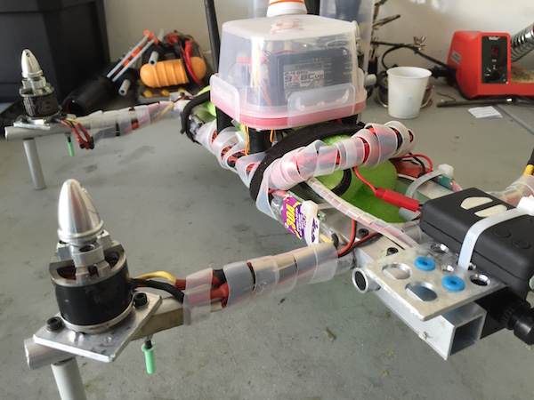
The completed frame
This post is not a complete tutorial. Rather, it’s a collection of notes that should be useful for you to refine and build your own drone frame. If after reading this you feel you want to build something simpler, give my custom DIY PVC frame a try.
Materials
The following list includes the most important materials I use for this design. You will need to adjust them if you plan on using different propellers.
-
For the arms, ½″ round aluminum pipe. You’ll need two 16″ sections, one for each arm. In addition, you’ll need two 4″ pieces for the arm support depicted in the main joint further below.
-
For the center elements, you’ll need two 16″ or more by ¾″ square tube sections. This leaves a few inches to play with arm placement depending on the gear you want to carry.
-
One appropriate plastic container to house the electronics. My current favorite is a certain 10oz square transparent container. The container should provide enough space for your flight controller, receiver and GPS module. The plastic needs to be strong enough to provide good support and protection to the electronics inside.
-
A few ear plugs to be cut in washers, for isolating vibration to the electronics.
-
24 M3x0.5 screws, washers and lock nuts of appropriate lengths. I’m using 1.5 and 2″, but your version might require different sizes.
You’ll also need some tools to drill and cut the aluminum stock as required. These are some of the tools I use to work in this type of frame – note you won’t need the tap and die set. I abuse my bench drill as well.
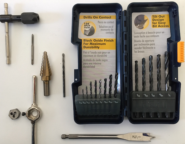
Some of my tools to work with aluminum
I won’t be covering things as the camera base or the lighting system on this post to keep the length of this post under control.
Main Joints and General Dimensions
The frame is composed of two central elements with perpendicular arms at the ends. The central joints are depicted in the diagram below, along with approximate measurements. You can also see a vector representation of this joint.
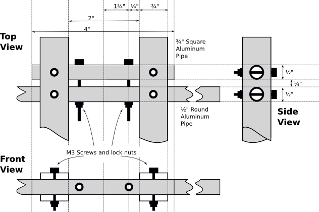
Main Joints
Overall, the arms should be 13″ apart to ensure a minimum 3 inches clearance between propeller tips. The length of the arms is 16 inches so as to provide clearance from the central body and reduce turbulence and vibration. 18″ arms would also work well and further increase the clearance.
For my builds, I leave a 2″ margin on one end of the central structure and a 1″ clearance on the other end. The 2″ side provides ample space to mount my suspended bridge, with my FPV and main cameras.
Frame Build Steps
Working with tools of any type is a risk. This risk is higher when working with sharp tools that are cutting through metal. Be safe and wear eye protection and gloves. If you have doubts about how to follow these steps, then stop and seek advice.
Start by cutting your aluminum stock. If you’re following my design instructions and intend to use 10″ propellers, go ahead and cut two 16″ sections of the square aluminum pipe. These will become the central members of the frame.
I use an electric reciprocating saw for this, although a rotating or band saw could be a better option.
After you’re done with the square pipe, cut the two 16″ and two 4 inch sections of round pipe that will become the arms and the supports.
At this point you can stow away your saw because it’s drill time.
Start with the ½″ holes in the sides of the central members. These will host the supports and the arms. Decide how much space to leave at each end for your gear and then mark the center of the holes (see the Side View section of the diagram above).
Make sure you leave around ¼″ between the edges of the holes. On what will be the rear of your drone, leave one″ between the edge of the square pipe and the border of the nearest hole. At the other end of the drone, leave 2″. This side will host your front-facing gear such as the FPV camera.
I open these holes using the ½″ wood bit you see at the bottom of my tool set. I just do that slowly and lubricate with WD-40. I could also use the conic bit you see above. After the holes are open, verify that the arms and supports go through. They should fit the holes without too much play.
Now put your ½″ bit back in its case and pull out your ⅛″ bit. We’ll use this for the M3 screws that will hold the frame together.
Each joint needs two holes connecting the supports and the arms together. The easiest way for me to do so is to mark the approximate location of the holes using the dimensions in the diagram, clamp each support and arm together and use the drill press to go through both sections of pipe. Make sure the centers of both sections are aligned.
Once these holes have been made, mount the arm and support to the central members. Pass the screws through the support and arm – the arms should go towards the center of the frame – and put the washers and nuts. Do not tighten them just yet.
At this point, you can proceed to drill the holes that go through the center members, the arms and their supports. Then place the screws, washers and nuts.
Your joint should now look like the one in the diagram above. After double checking that all screws are in position and with their washers in place, go ahead and tighten them. If you’re using steel screws like me, then be careful with your torque as you can badly warp the aluminum, which would reduce its integrity.
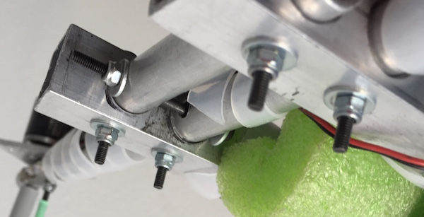
A completed rear join
After finishing with both joints, you should have your basic H4 frame in good shape. Here’s a picture of one of my completed joints. Notice the use of washers.
Motor Mounts
I won’t go into the power distribution and ESC mounting. I regularly solder my own distribution harnesses – with two extra JST female plugs for additional things such as BECs or lights. In fact you can see one of them in the first picture of this post.
For the version I’m showing on this post, I’m using my custom motor mounts.
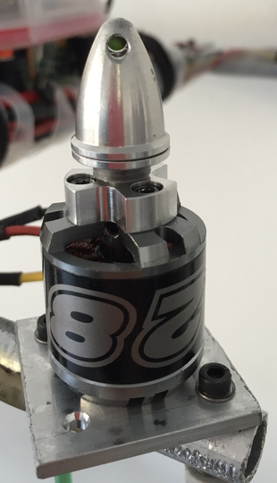
Motor Mounts
These require two holes on each arm to accept the two M3 2″ screws, washers and lock nuts that I use. The 2″ also serve as clearance that helps keep the propeller tips away from the grass blades (or the ground!).
I use plastic inserts that hold to the M3 screws and on top, pieces of a certain water pipe that fits snugly, is light weight and extends to provide a couple″ of ground clearance. This is visible in the first picture of this post.
Mounting the Electronics Container
The plastic container that will house the flight controller and other electronics needs to be in the center of the frame. The dimensions of this frame leave space for at least a 2¾″ by 2¾″ container, which is just right for the electronics I use.
Basically I drill the container’s lid at each corner. I also make corresponding holes in the top and bottom of the square aluminum center members. The bottom holes are larger, to allow the head of the screw to go into the pipe.
I use 2″ M3 screws to hold everything together. Through the screw, I place a hollow plastic standoff and a large washer. Then I insert the foam washer made by cutting about half of an ear plug – you’ll need to open a hole through the plug. Then comes the plastic lid, a nylon washer and a lock nut on the other side.
Lightly tightening of the nuts provide for level adjustment of the lid – now the electronics tray. Don’t over tighten the nuts because you want the foam to be able to absorb vibration.
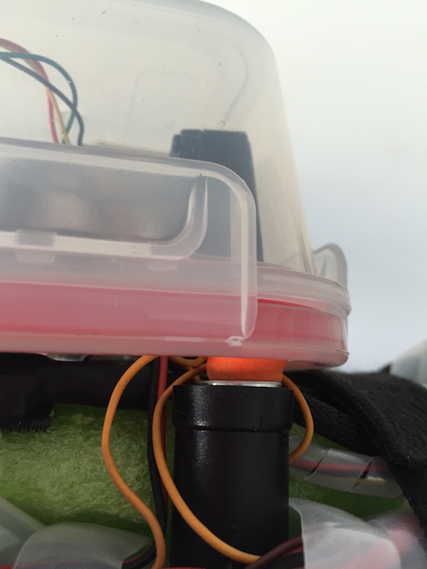
Electronics Container
On the inside, I’ll mount two strips of vibration gel to hold the flight controller in place, making sure that the nuts and bolts are well away from it. Landing upside down could ruin your electronics otherwise. You can see the screws in the picture below.
Also, you can see the mounting of the UBLOX GPS module. Normally I cover them with transparent heat shrink and hot glue them to the inside of the container. This provides total view of the sky without protruding appendages.
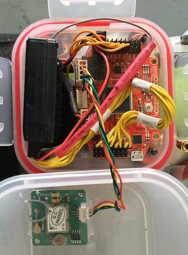
Electronics Mount
If you look carefully, you’ll also see the hole at the bottom where the ESC signal wires, the BEC power and the telemetry cables come through. Make sure to have all the required holes open before mounting the container.