As I've said before in this post about NTM motors, I use them in a few of my mid-size drones. I think that in the 400mm to 500mm range, these motors perform well enough to fly recreationally and as long as you stay out of dust and land with the right side up, they won’t disappoint.
But the motor mounts themselves don’t work well for my setup – and I suspect others might have similar issues.
In my current favorite model, the arms are attached directly to the mounting plate using 2 of the 4 positions. While this hasn’t been a problem with other motors / mounting hardware, the NTMs break on average once every two hours of flight. Here’s a sample…
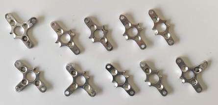
Broken, pristine and in-progress motor mounts
My guess is that in-flight vibration combined with screw pressure cause metal fatigue that ultimately breaks the mounting plates at the thin areas by the mounting screws. This can be exacerbated by the shearing force of the screw head and the torque caused by only using two of the mounting positions.
Usually the plates develop visible cracks that can be spotted in the post-flight inspection (you inspect your models before and after flight, right?), but after my first in-flight break, which of course caused the quad to enter acro auto-landing mode, I decided it was enough.
Let’s build a tough mounting plate
I decided to build my custom mounting plates out of 1½ inch aluminum bar. With its 3 mm thickness, around twice the stock, this should increase resistance. I was also concerned about the small amount of aluminum around the screw holes. Looking closely enough, it was evident that this was the weakest spot in the mount.
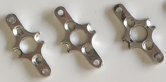
Notice the place where the plates broke
Fatigue and stress would surely manifest there first and indeed, in all cases this has been the failure point. I settled around a 36mm aluminum square in which I would drill all the required mounting holes. The resulting mounting plates would be significantly heavier, but also significantly stronger.
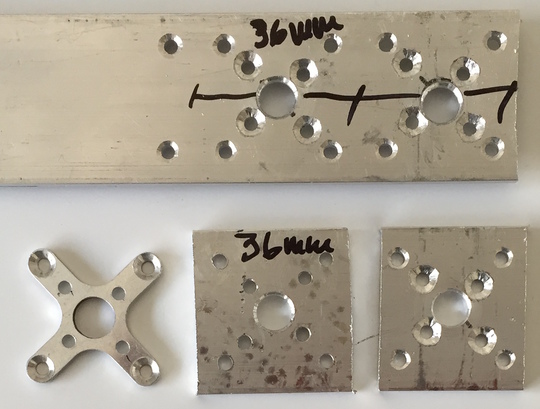
Custom square motor mounts in various levels of development
The picture shows the different steps – drilling on the complete bar at the top, then two separated bases before and after the finishing steps in the holes. On the left, a stock motor mount. Since I don’t own a suitable saw, the cuts on the bar are not perfect so the bases are actually square-ish, however this is not noticeable when mounted to the arms.
All the holes were drilled with an ⅛ inch high speed steel drill bit and finished with a conical bit to accept the stock conic head screws. This also happens to be perfect for the M3/0.5 screws I use for mounting the base to the frame.
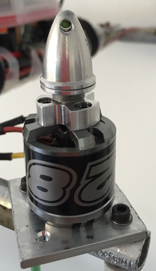
A finished mount
Note that in this motor, the mounting holes are not in a square. Because of this I think the best approach is to use a stock mount to mark the location of the holes in the aluminum bar. As always, measure twice and cut once.